Home ¦ Direct Cable Connections ¦ Null Modem connections ¦ Serial Ports ¦ Technical Page ¦ Build a home LAN
On this page:
Here are several diagrams and tables explaining serial port and null-modem configurations. If you are seeking further detail regarding serial port hardware settings, then find out More about com ports.
A serial port can consist of either a 25 pin port adapter called a DB-25 or 9 pin adapter called a DB-9 port adapter. Whether the port is a 9 pin or 25 pin it can accomplish all of the same tasks that serial port communications have been designed for.
Each adapter can be a male type connector or a female type adapter. Generally a com port on the back of a computer is male for the serial ports but it may not necessarily be. Below are diagrams of a DB-25 and DB-9. (Each diagram on this page is the view you see when you look into the end of the cable from the outside of the cable.)
The "o" characters represent holes, the "." characters
represent pins.
A DB-25 looks like this...
Diagram #1
Female:                        Male:

_____________________________  _____________________________
\ o o o o o o o o o o o o o /  \ . . . . . . . . . . . . . /
 \ o o o o o o o o o o o o /    \ . . . . . . . . . . . . /
  -------------------------      -------------------------
And a DB-9 is like this...
Diagram #2
Female:        Male:
_____________  _____________
\ o o o o o /  \ . . . . . /
 \ o o o o /    \ . . . . /
  ---------      ---------
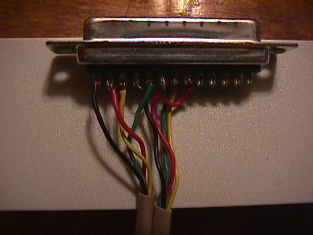
Each pin has a number assigned to it. When connecting null modem, for example, it is important to know these numbers in order to select the correct cables, or when making your own cables. Image of the cable I made.
| DB-25 Connector | |||
|---|---|---|---|
Chart #1
|
Chart #2
|
||
| DB-9 Connector | |||
Chart #3
|
Chart #4
|
||
If you are seeking to buy a null modem adapter, or trying to make your own cable, you should know what pins need to be switched in order to make null modem. Below is a chart of what pins go to what on the other end. Only 8 pins are used in a null modem, therefore I will only show those eight here.
|
|
|
Below translates the pin number with the wire name.
| Chart #8 | Chart #9 | ||||||||||||||||||||||||||||||||||||||||||||||||||||||||||||||||||||
|---|---|---|---|---|---|---|---|---|---|---|---|---|---|---|---|---|---|---|---|---|---|---|---|---|---|---|---|---|---|---|---|---|---|---|---|---|---|---|---|---|---|---|---|---|---|---|---|---|---|---|---|---|---|---|---|---|---|---|---|---|---|---|---|---|---|---|---|---|---|
|
|
For further questions, spelling corrections, or other, mail Acclaim@geocities.com.
Home ¦ Direct Cable Connections ¦ Null Modem connections ¦ Serial Ports ¦ Technical Page ¦ Build a home LAN