

| |
| |


|


| |
| |


|
Trigonometry was figured out about 200BC by Hipparchus. Little did he know that his discovery would be used to explain the physics of how a bicycle wheel is held together using little pieces of wire! Technically it is possible to make bicycle wheels using very strong string instead of metal spokes, due to the physical dynamics of a spoked wheel. The spokes in a built wheel are under tensile, not compressive, forces. A wheel is held in shape by all of these tensions balancing out throughout the hub and rim. When a bicycle is ridden, the support forces holding up the bike are from the spokes at the top of the wheel, the hub 'hangs' from the top of the rim. Even though the spokes at the bottom of the wheel undergo a compressive force from the supported weight, the compression is never enough to remove all of the build tension (at least in a properly built wheel). Lately bicycle wheels have been coming out that use fiber spokes, and emergency repair spokes are around that are also a flexible fiber. These fiber spokes work for the reasons just discussed, the build and dynamic tensions want to stretch these fiber spokes. This page will try to give a simplified look at how Trigonometry applies to a spoked wheel, and how it can be used to determine the length of the spokes when all you know are the sizes of the rim and hub, and the lacing pattern.
On this page I have several figures to explain how Trigonometry works with spokes. I kept the lines of the figures basic colors for ease of understanding, and for those that have simpler computers that can't support a vast array of colors. Figures 1 and 2 have some lines that are the same color, these are the RED, PURPLE and BLACK lines. In the text, references to the RED line of Figure 1 are called RED[1] and those for Figure 2 are called RED[2]. The references to the PURPLE line of Figure 1 are called PURPLE[1] and those for Figure 2 are called PURPLE[2]. And the references to the BLACK line of Figure 1 are labeled BLACK[1] and those for Figure 2 are labeled BLACK[2].
|
THIS PAGE IS ARRANGED INTO THE FOLLOWING SECTIONS: BASIC TRIGONOMETRY PRINCIPLES RADIAL SPOKE FORMULA RADIAL WHEEL STRESS FACTORS CROSS-LACED SPOKE FORMULA CROSS-LACED WHEEL STRESS FACTORS |
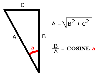
Laws of physics explain how the sides of triangles interact with each other, and how they function. The triangle is one of the strongest geometric forms for physical objects, since you cannot distort one side (by compression or extension) without putting forces on the other two sides. Two of the laws of Right Triangles come into play for determining spoke length. One law that applies is that the length of the longest side, the hypotenuse, equals the square root of the sum of the squares of the two shorter sides. The other law that applies is the Cosine law of the angles in Right Triangles, which is the ratio of the lengths of the shorter side and the hypotenuse. In the figure below A is the hypotenuse and B is the side of interest. The cosine of the hypotenuse and side B can be determined if you know the value in degrees of angle a. These two laws are used in the formulas to calculate the spoke length.
|
A cross laced spoke has three main force vector triangles that affect it's length, radially laced spokes only have one. In a fully built wheel there are many other force vectors that affect each spoke, but these force vectors don't affect the length of the spoke, they affect the characteristics of the wheel. I will discuss a radial spoke first since it is simpler.
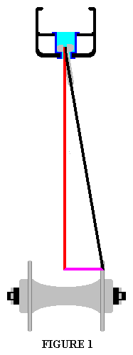 Figure 1 to the right illustrates the single main force vector triangle that affects a radial spoke's length. It is comprised of the spoke's force vector, which is the BLACK[1] line, the hub's force vector, which is the PURPLE[1] line, and the force vector generated by the spoke that holds the wheel together, which is the RED[1] line. The length of the RED[1] force vector is determined by the diameter of the rim, and it is the only force vector that is not also a physical object. In a real wheel this force vector continues to the center of the axle, but the section displayed in the figure is what is used by the formula to calculate spoke length. The length of the PURPLE[1] force vector is the distance between the center of the hub and the flange the spoke anchors to. The formula to figure out the length of the spoke involves the RED[1] and PURPLE[1] force vectors.
The force vectors of Figure 1 apply to the spoke length formula for radial spokes like this:BLACK[1] = SL; the Spoke LengthWhen you apply trigonometry to these values you get the following formula:
RED[1] = RRSP - HSR; the Rim Radius plus Spoke Penetration minus the Hub Spoke Radius
PURPLE[1] = HFO; the Hub Flange OffsetThis is the Radial Spoke Formula on the Home page:

The following discussion applies to the force vectors shown in Figure 1 above. These force vectors, in addition to determining the length of a radial spoke, illustrate the main stresses the spoke is subject to on the wheel. They also can be used to explain how a radially laced spoke deals with, and affects, the ride quality of the wheel. Everything from suspending the bike and absorbing road shock to giving the wheel it's lateral strength qualities.
The BLACK[1] line represents the spoke and it's force vector. This force vector serves the dual purpose of centering the hub in the rim and giving the wheel it's lateral strength. The other two lines represent the dual force vectors generated by the spoke, that are not a part of the spoke, but are the force vectors that determine the physical qualities of the wheel. The RED[1] line is the force vector that holds the hub in the center of the rim. This line is the only force vector in a radially spoked wheel that does not have a physical member. The PURPLE[1] line represents the force vector of the hub's lateral dimension, and is related to the lateral strength of the wheel.
The RED[1] force vectors of the spokes at the top of the wheel hold the bike up. The force at the bottom of the rim from the weight of the bike splits into two forces, one travels around the front of the rim and the other travels around the back of the rim, and they meet at the top of the wheel. These forces then find the nearest spokes and turn down the RED[1] force vectors to the hub. When this happens, the BLACK[1] force vectors keep the RED[1] force vectors from wanting to push the rim away from the hub. If the rim was made out of a metal that had absolutely no give, all of the weight of the bike would be suspended from only two or three spokes. The two closest spokes to the top, if no spoke was exactly in position at the top of the wheel, and three spokes if one spoke was exactly at the top, the one exactly at the top would take half the force and the two next to it (that go to the other hub flange) would split the remaining half. For this very reason, if you hit a large object that deforms a rim spoke hole, the hole that gets damaged is one at the top of the rim at the time of the impact, not one at the bottom like some would think.
In a real wheel, the forces the rims sees while supporting a ridden bike want to flatten the rim, that is make it shorter and wider (from a side view). The spokes at the top of the wheel mainly support the weight of the bike. The spokes at the front and rear of the wheel keep the rim from flattening, so while they do not specifically support the bike, they do absorb some of the force holding the bike up. The spokes at the bottom of the wheel have their build tension removed equal to the weigh the wheel is supporting. Since the spokes at the bottom have their build tension relaxed, if the build tension is not high enough, the pressure on the threads of the spoke and nipple relaxes to the point that when the pressure returns (as the wheel spins), the forces will want to unscrew the nipple. In a wheel built with a high spoke tension, when the build tension is relaxed by the weight being supported, there is still enough tension on the threads of the spoke and nipple to keep the nipple from loosening.
The lateral strength of one side of the wheel is related to the PURPLE[1] force vector, which also represents the dish of that side of the wheel. The longer this PURPLE[1] force vector is, the greater the lateral strength. This is why the drive side of a multi-speed rear wheel has less lateral strength than the non drive side. The lateral strength is also affected by the position of the spoke on, and the diameter of, the hub flange. The farther away from the center of the wheel's axle the spoke anchors onto the hub's flange, the greater the lateral strength of that side of the wheel. This is for a couple of reasons. One reason is that the spoke becomes shorter. The shorter the spoke the less the spoke stretches for a given load. For example, if the metal the spoke is made of has a 10% stretch for a given load, a 10mm spoke will stretch 1mm and a 100mm spoke will stretch 10mm under equal loads. The other reason is that the place where the spoke anchors to at the hub becomes closer to the rim. This increases the spokes anchor angle at the rim. The closer the spokes anchor angle at the rim is to a straight vertical line, the less lateral strength that side of the wheel has. This is also why lacing radial spokes with their heads on the inside of the flange gives them more lateral strength.
When you build a wheel with radially laced spokes, you should not grease the spoke threads like you can with cross laced spokes. You can use a spoke prep that has locking characteristics, but not regular grease. If you do, the vibrations and tension cycles the spoke undergoes when the bike is being ridden will slowly unscrew the nipple. A radially laced spoke does not have a crossing spoke that dampens any vibration, and it will resonate like a guitar string until the energy of the vibration is dissipated. The tension cycles the spoke undergoes when the bike is being ridden is from the weight being supported by the wheel, which was discussed two paragraphs above. The reason that these forces unscrew a radial spoke but not a cross laced spoke has to do with the BLACK[1] force vector. Since this force vector is the spoke itself, the tension on the nipple threads is even all the way around the nipple. Since this tension is even there is no dynamic friction on the threads. When the spoke is greased and the nipple and spoke threads are undergoing a tension cycle, every time the tension becomes greater it causes the nipple to unscrew a tiny bit. If the threads are not greased, the friction of the contact of the spoke and nipple threads prevents this from happening.
A built wheel that is not supporting any weight has numerous force vectors it is dealing with from the build tension of the spokes, the pressures on the rim, and the stresses on the body of the hub. Far more force vectors than the addition of the three represented in Figure 1. The force vectors from each individual spoke fight with all the other force vectors affecting every other spoke, a built wheel has hundreds of force vectors that are fighting with each other. All of these force vectors need to balance each other out in order for the wheel to stay round and true. The forces that are generated from the action of supporting the weight of the moving bike fight with the hundreds of force vectors keeping the wheel round. All these force vectors fighting with each other are the reason spokes will loosen and the wheel will go out of true easily in poorly built wheels. This is also the reason that large stresses and shocks (such as from hitting a large pot-hole or rock, or from going down hard) throws wheels out of true.
With cross laced spokes there are three triangles associated with each spoke that determine it's length. These three triangles are:1) A triangle that is essentially the same as the one for a radially laced spoke described above and shown in Figure 1. This triangle deals with the spokes lateral properties.
2) A large triangle associated with the spoke's vertical force vector directly from the spokes attachment to the rim to the center of the hub, the spoke head's horizontal displacement from this force vector, and the spoke itself.
3) A small triangle at the hub associated with the hub's spoke hole where the spoke's head anchors to the hub, the center of the hub, and the spoke's vertical force vector that goes from the anchor point at the rim to the center of the hub.
 Triangles 2 and 3 are shown in Figure 2 to the right. Triangle 2 is comprised of the BLACK[2], PURPLE[2], and BLUE lines. Triangle 3 is comprised of the BLUE , GREEN, and RED[2] lines. When you know the Hub Flange Offset (HFO), the Hub Spoke hole Radius (HSR), the Spoke Anchor Angle (SAA), and the Rim Radius plus Spoke Penetration (RRSP) you can calculate the length of the spoke. The SAA is dependent on the number of crossings on the spoke. These values are used in the formulas to calculate the needed information from the three triangle. While this seems complex, the property of mathematical convergence combines the three formulas into one. The result is the main formula.
 The first things you need to calculate the spoke length are the values for the GREEN and BLUE lines of the small triangle of Figure 2, to the right. To figure the length of the GREEN line you multiple the Cosine of the SAA and the HSR. The Cosine of the SAA can be found for most spoke crossings and wheels on the COSINE page. The HSR is represented by the RED[2] line. Once you know the value of the GREEN line you calculate the value of the BLUE line by squaring the values of the GREEN line and the RED[2] line, adding them together, and then taking the square root of the result. The mathematical formula looks the one below;

 You then need to calculate the distance from the rim to the hub flange at the dimension of where the spoke will anchor. This is represented by the PURPLE[2] line of Figure 2 and the BLACK[1] line of Figure 1, to the right. To calculate this value you first subtract the value of the GREEN line you just calculated from the RRSP, this gives the value of the RED[1] line. The value of the PURPLE[1] line is the HFO. You then square these to values, add them together, and then calculate that square root. Mathematically the formula looks like the one below;

You now have what you need to calculate the spoke length, which is the BLACK[2] line. The BLACK[1] line is the same as the PURPLE[2] line. The spoke length is square root of the sum of the value of the PURPLE[2] line squared plus the value of the BLUE line squared. When you combine the two formulas together you end up with the following;

Since the first two formulas give square roots that then get squared, these operations cancel each other. The formula reduces to this;

This formula is the main formula, and the colored lines apply to the real wheel like this;BLACK[2] = SL; the Spoke Length
RED[1] = RRSP - (HSR x COS(SAA));
the Rim Radius plus Spoke Penetration
minus the Hub Spoke Radius multiplied by
the Cosine of the Spoke Anchor Angle
PURPLE[1] = HFO; the Hub Flange Offset
RED[2] = HSR; the Hub Spoke Radius
GREEN = (HSR x COS(SAA)); the Hub Spoke Radius multiplied by the Cosine of the Spoke Anchor Angle
In a cross laced wheel, while the overall effect of the spokes is similar to a radially laced wheel, that being the support of the bicycle, there are a number of differences. I will explain the main forces that affect a cross laced spoke and compare them to a radial laced spoke. In the rest of this section the BLACK[1] and BLACK[2] lines in the two figures will represent the same force vector, which is also the spoke, so I will call them both the BLACK line for simplicity.
|
|
The main force vectors affecting cross laced spokes are shown as the RED[1] and PURPLE[1] lines, just like in a radially laced wheel. The PURPLE[1] line represents the lateral forces generated and absorbed by the spoke. The RED[1] force vector represents the build tension on the spoke and the suspensive forces that are placed on the spoke when the bicycle is being ridden. This is the major force vector affecting and controlled by the spoke. The major difference between a radially laced spoke and a cross laced spoke is illustrated by the PURPLE[2] force vector. Unlike in a radially laced spoke, the physical spoke does not line up with this force vector.
In a cross laced wheel the physical spoke does not line up with it's major force vector. Since the spoke does not physically line up with it's major force vector, a triangular shape is formed by the force vectors. This triangle is responsible for transferring torque from the hub to the rim. This triangle also gives the cross laced spoke a softer ride. Since the major force vector of the spoke does not line up with the spoke, it has to be balanced by an equal force coming from the other spokes on the wheel. When the wheel hit's an object, the shock wave splits around the rim and travels to the top of the rim (which was explained in the RADIAL WHEEL STRESS FACTORS section above). The shock wave then travels down the nearest PURPLE[2] force vectors to the hub. As this happens the top of the rim wishes to move away from the hub. In a radially laced wheel, when the shock wave tries to move the rim away from the hub it is met with the great resistance of the spokes at the top of the wheel. In a cross laced wheel the shock wave can cause the rim to move in relation to the spoke, due to the large triangle illustrated in Figure 2 (the movement would want to be to the right in the figure). Since this large triangle is balanced by the other spokes in the wheel, the shock wave hitting this triangle can cause movement because the balancing force travels through the rim, and all the other spokes have similar force vector triangles that also have give. When the shock wave dissipates the rim returns to it's normal position. The movement of the rim in relation to the hub absorbs some of the shock. The greater the number of crossings (to the point of reaching a 90 degree angle between the BLACK and BLUE lines of Figure 2) the easier it is for the rim to move and the more shock absorbing the wheel becomes. This shock absorption movement is different than the torque transfer properties of the wheel because the shock wave affects the spokes and the rim unevenly and from many directions, whereas torque transfer affects all the spokes and the rim evenly and from only one direction.
When comparing the lateral strength of a cross laced spoke to a radial laced spoke, you can see in Figure 2 that the spoke is closer to the center of the hub on a plane that is represented by the BLUE line. Since the head of the spoke is on a plane that is closer to the center of the hub, the diameter of the hub flange is essentially reduced. This causes the spokes angle at the rim to lessen, and the angle at the hub to increase. The closer the spoke angles toward the RED[1] force vector, the easier it is for a lateral force to move the rim. An easy way to comprehend this is to imagine that the spokes went straight out the sides of the rim, any force that would move the rim sideways would have to stretch a spoke. If the spokes went straight down to the center of the hub (if the spoke was the RED[1] line), pushing the rim sideways would be very easy. This is the same principle that gives the drive side of a rear wheel less lateral strength than the non drive side, the angel of the spokes at the hub and rim in relation to the force vector from the center of the rim to the center of the hub. In a cross laced wheel the spokes are longer than they would be in a radially laced wheel. The longer a spoke is the easier it is to stretch, and this also reduces lateral strength. These reasons are why many track wheels have high flange hubs. The larger the diameter of the flange, the shorter and stronger the spokes, combined with the resulting angles of the spokes at both the hub and rim that make the wheel firmer, all these factors add up to give the wheel higher lateral strength and better torque transfer performance.
For the ability of a cross laced wheel to transmit drive torque efficiently, and a radial wheel not to, you need to study Figure 2. In a cross laced wheel the spoke is the BLACK line, in a radial laced wheel the spoke would be the PURPLE[2] line. Imagine the hub trying to turn clockwise. If the spoke is the BLACK line, when the hub rotates it has a direct force vector that pulls on the rim. If the spoke is the PURPLE[2] line (which it is in a radially laced wheel), there is no force vector to transfer the rotation of the hub to the rim.
The radial spoke would stretch until two things happen, first; the spoke moves out of line with the PURPLE[2] force vector which gives it the characteristics of a cross laced spoke, second; the increase in tension on the spoke from it's stretching equals the drive torque force turning the hub so it can't stretch further. When these two things happen the drive force gets transferred from the hub to the rim. But there can be a large movement of the hub to the rim before these forces balance out. This means that if you pedal lightly, the spokes would not stretch much before the forces reach equilibrium and the bike gets driven forward. If you sprinted or climbed a hill, the spokes would stretch quite a bit before the forces reached equilibrium and the drive force was transmitted to the rim. The result is called 'wind up'. The harder you pedal, the more the wheel will 'wind up'. If you pedaled so hard the drive force plus the build tension matched the spokes maximum load capability, you would start snapping spokes. The fewer spokes the wheel has the more it will suffer from these effects.

