 My Project ...
 My Project ...
So what have I been building with these tools you ask. A robotic kite flyer is the answer. I over heard a discussion one day where some hobbyist engeer types were discussing a vision system. One of them proposed that the system could be used to fly a kite. This seemed like over engineering to me. Having played with two line stunt kites, I guessed that by monitoring tension and direction of the lines you could fly a kite. So just for the heck of it I decided I was going to build a robotic kite flyer, a blind robotic kite flyer.
OK, so I haven't completed the kite flyer yet. I have most of the mechanics hooked up. I have an 8096 computer board, supplied by a friend, mounted to the device, and I'm at point where I have to do some manual flight tests to determine what the data during flight will typically look like. After that I need to program the 8096 board to not only monitor inputs but to control the motors that control the kite lines.
Return to home page Sign guest book View guest book
Email questions to RJKuhn_2000@yahoo.com
Last modified: 8 June 2002 by R. J. Kuhn
This is a template of the Pascal source, assembly code, and ROM file (i.e. binary) for the 8096 board that runs the robotic kite flyer. The ROM file is the binary produced by this assembly code with a header added so that it can be loaded into DebugCPU. The assembler and debugger I used to work on this code are available on this web site.
To run this ROM file under the debugger type "DBG8096.exe CTIKitPC.R96". Once the debugger starts you can run the code by typing "g =3000" and the code will start to execute. Notice that the value next to the PWM (Pulse Width Modulation) output will increase in value, and once it reaches FF, it will jump to the lowest value. This will continue going up and then down at equal rates. On the actual hardware this corresponds to an LED that increases and then decreases in brightness. Now move the ADC input #6 (the slider input in the lower left of the group of sliders) to the right. The PWM output will now increase in value slower and instead of jumping to the lowest value it will decreasing in value at the same rate. On the actual hardware, ADC input #6 is hooked up to a switch that controls whether the 8096 board is sampling the data from the other ADC inputs or if its in a wait state not sampling the input data.
Here's a picture showing a full view of the robotic kite flyer.

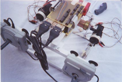
Here's a few more showing the motor assembly and line reals (fishing reals).

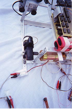
And finally a few showing the 8096 board electronics and the direction sensors (gutted joysticks).

I haven't uploaded the CAD DXF design file yet.