| Stearman construction continued....... |
 |
| (click on any picture for a larger view) |
| The landing gear is mounted. The gear itself is made from aluminum and mounts directly to holes pre installed with blind nuts in the fuse. The gear cover piece is installed. There are two access holes in this cover to get to the landing gear mounting screws but I haven't opened them up. I'll do that if I need to later for reapir or to re-tighten. |
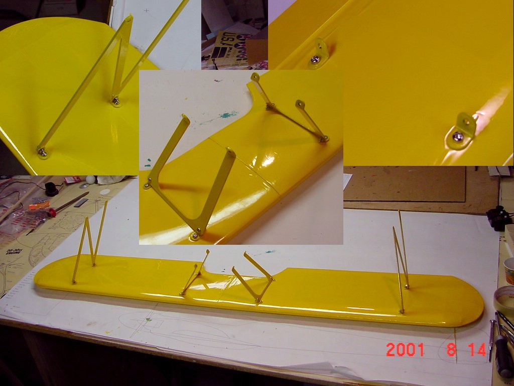
| The wing struts are pre made from aluminum and attach to the wings using pre-bent brackets. There are four different bracket shapes and each one goes in a certain location. The 'N' struts have to be mounted a certain way. The short leg is on the forward side. Make sure you pay close attention to the instructions when mounting these or your wing incidence will be off and the plane will not fly right. The only problem I had is that the nuts used for the screws mounting the stuts to the brackets are not self locking. I plan on replacing these with nylocs. |
| The motor is mounted on two supplied beam mounts. Depending on which motor you use will determine how they are located. The firewall has scribed reference marks already on it. You need to measure from these marks for the proper beam spacing. Make sure you locate the beams properly using the molded-in lines on them relative to the scribed vertical line on the firewall. You can see where I drew a reference line for the upper beam and spotted one of the mounting holes. Furnished blind nuts are installed on the backside of the firewall.. |
| The tail wheel is of conventional construction. You need to remember to install the hinge fitting prior to bending the wire. the wire is stiff so some force is necessary to form it. You need to slot the tail post and provide a releived area in the rudder to accept the hinge. |
| I couldn't resist putting the plane together to get an idea of it's final size. The wing strut bracket mounting holes are pre-located at the factory and make for a perfect alignment of the wings. I'm really pleased with the color scheme I chose. It will be sure to set it apart at the field. There is still lots more to be done but this is a very enjoyable project so far...... |
| Back to the Stearman main page |
| These are the parts for the fuel tank. The tank capacity is 270cc (9.1oz) and typical of most any fuel tank you'll find. Kyosho shows a three line installation but I went with two (main feed and vent) since I'll be using a DuBro fuel valve. The tank fits perfectly and you can see that if you wanted to go with a larger tank you would be hard pressed to get it to fit. If you do it will require cutting and encroachment into the Rx/battery area. |
| The OS52 4-stroke installed. One change I made was to use 3mm nylon locknuts on the screws that mount the motor to the beams. Kyosho should have included these. You can also see in the inset photo the fuel tank installed with silcone adhesive. The motor just fits at the specified distance from the firewall without the throttle arm hitting the engine mount. |
| Here's where you start to make what makes the Stearman recognizable; the Continental R-670 engine. The vacu-formed halves will be glued together, trimmed and detailed. Kyosho furnishes everything you need to detail the engine. |
| On to the next page of construction photos........ |


