Lithium Ion pack development

    The lead acid pack was a great initial solution for proving the concept and doing field tests.  It's hardly the stuff of my dreams, however.  It doesn't carry enough energy to make the electric drive worth while.  Also, to meet weight criteria I had to choose a relatively small pack.  Because of this the pack performs poorly in this high power application (around 50% efficiency).  For about 2x the battery pack weight I found enough lithium ion battery to provide 5x the AH capacity and achieve over 90% nominal operation efficiency.  This should increase the bike range on flat ground at least 5 fold.  In theory it should be closer to 10 times better.  There is, of course, some risk with Lithium Ion batteries: they can overheat and vent (or even worse, catch fire).  I did find a PDF online documenting some tests on the particular cells that I have come in possesion of.  The test results are courtesy of Ivan Galysh and Gil Dutchover and can be found here.  Having acquired enough good lithium ion laptop batteries for a ridiculously cheap price I set out to build a lithium ion pack.  These are the challenges I had to overcome and features that I feld it needed:

    To assemble the cells I decided to solder everything together (using tabs already on the batteries).  I wish I could have tab welded everything together with copper sheets, but I don't have such a machine and they run minimum $500.  For developing a monitor and control system for the pack I considered analog devices at first.  This gave me a big head-ache real fast and I talked to Bill Bailey, the guru at Birdwell Machine.  From him I learned how much simpler it would be to use inexpensive micro CPUs like Atmel's AVR family.  Atmel's atmega8535 are especially attractive, offering 32 I/O ports, 8 - 16 MHZ speeds, 8 analog inputs, onboard PWM channels and even free C compilers and simulators.  For about 30 bucks (the cost of the programmer) and $5 per chip I was in business.  It really is quite amazing.  I am still scratching my head as to why in all the digital circuit and control classes that I've taken at U of W I've never even heard of atmega.  This technology just makes so many problems go away!  And it couldn't have been budget constraints, these controllers are cheaper than what the school pays for keyboards.  Anyway, I set out to develop the circuits and programs to run the monitoring system and a custom charger.

prog station
  Atmega8535 programming station (programmer interfaces with a PC).

batteries
  Freeing the 18650 cells from their laptop prison.  A little prying/cutting action, and pop!

temp
  Testing temperature sensor.  It's cheap but it works pretty well.

proto
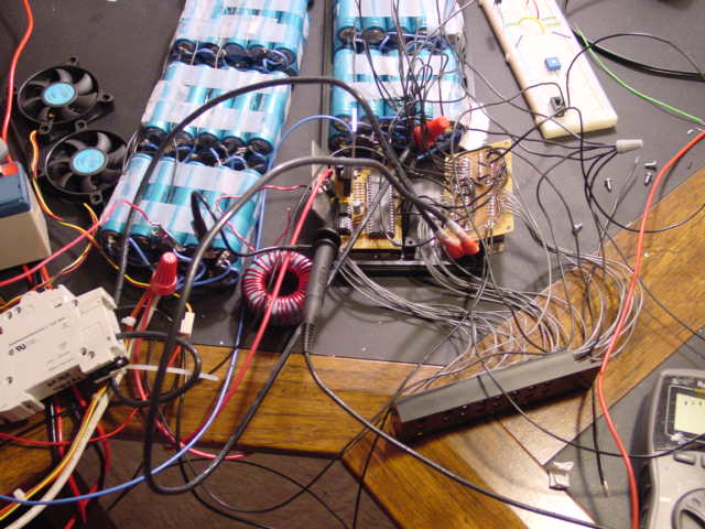
  Complete prototype of the system including boost mode charger.  Each cell voltage and temperature is monitored.  A pair of small fans provide cooling.

boards
  Prototype boards - amazing how things become compact.

ledbank
  LED bank.  The 1st row includes an OK light and a current meter.  The next bank is UV/OV.  Farthest bank on the right is over-temp.

test
  Initial assembly and test of the prototype boards.  Yes, this was a royal pain the ass. Next time I won't hesitate to shell out $100 for pro PCBs.
charging
  Charger in action.  The charger uses atmega's onboard PWM channel to control the boost converter.  It holds 3 plus minus .5 amps drawing about 10 amps from the big lead acid car battery on the left.

lights
  The charge level is topping off and the charger is throttling back.  Note the LEDs lighting up indicating OV condition.

scope
  Oscilloscope on the PWM signal from the charger.
boxes
  Battery pack in the machine shop.  The cases and fan ducts are made of glued ABS.  I sealed the boxes with some silicon gasket maker.

ducts
  Lith-Ion pack finally on the bike.  It looks like something from the Jettsons...  The fan ducting is bound to turn some heads.
clock
  That's not 4 PM by the way.  Did I mention that I'm a masochist?  Well I'm not really, but I did work pretty hard on this.

userinterface
  Top half of the battery pack.  The LED bank is positioned and angled just right so the extra bright 3000 mc LEDs just about blind you when something's wrong.  The two switches in the middle are for fan over-ride and the charger.  The main breaker is on the right side.

itscool
  Julie approves as the bike sits charging.  "Can I go do wheelies now?"


1