Design

    The ultra-capacitor drive was a good exercise, but unfortunately not very practical.  Ultra-capacitors are expensive and don't pack enough energy.  Furthermore, the effeciency readings Ben and I took show that the controller in Boost mode is horrible.  It could be improved, but it would never be as good and simple as a straight up Buck converter.  I realized that until the technology comes my way I will have to rely on simple batteries.  My first choice will have to be Lead-Acid.  They won't take a big bite out of my wallet and will be sufficient for a prototype.  They are also bullet-proof.  From my experience on the EV team I found that people in the EV business generally beat the crap out of their batteries and get away with it.  It is possible to pull horrendous currents out of them.  The only draw back is that they don't last very long and below the bells and whistles are still primitive.  I also have a Lithium Ion pack that I acquired almost by a miracle for the same price as the lead-acid.  These batteries do require special attention, however, and I still have to make the protection circuits.  Unfortunately, because my lead acid batteries cannot be recharged in a quick manner regenerative braking will have to stay on hold.  There is some promise with the Lithium Ion (can be safely recharged at 3x the rate), but that is in the future.
    For now, I'm happy with a motor on the frame.  Finding good cheap motors for this application was the next challenge.  I finally settled on a single EV Warrior beast.  These are about 4" in diameter and 2.5" long.  For the money spent (~$25 on eBay) it can put out plenty of torque and power (peak 1.5 HP possible).  It can run on 24 V and soak over 50 amps for a minute.  It seems to take 100 amps for a second or two without complaining.  It's not very effecient and is a pain in the ass to mount, but you get what you pay for...
    While I was working on my own buck controller I was having issues with switching noise and motor voltage spikes.  Snubber circuits and filter caps helped, but I would have to read a lot more books and spent a lot more time refining it.  I finally decided to cheat and bought an original EV Warrior controller complete with harness on eBay.  I think it was a great buy for me (but once again, you get what you pay for).  With these peices in place it was time to tackle the mechanical side of things.  Luckily, through my experience in the UW Formula SAE I had very good knowledge of SolidWorks.  And having worked at Birdwell Machine for two years I had a lot of experience in machining and fabrication in general.  Even better yet, the Birdwells were willing to let me use any machine I wanted to and were happy to offer advise where needed.


  Tiny Power-Sonic 2.9 AH leads (~2.9 lbs)   


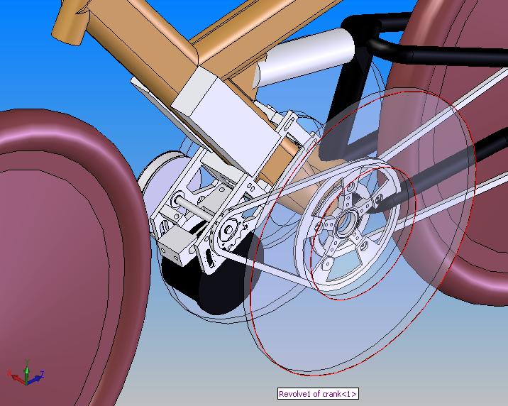
  EV Warrior motor (note complete lack of mounting features)

  EV Warrior controller & harness (note thumb throttle)


  Julie feels the power...

  My own controller exiled to the top shelf

  EV Warrior throttle and display.

Mechanical

   
I started out by carefully measuring the bike and creating a model in SolidWorks.  It turned out to be fairly accurate.  Initially I pondered manufacturing a gearbox or a CVT belt drive, but such a project would be quite hefty and expensive.  I went ahead and actually designed a CVT based on a belt from Jason Industrial, but a comparison chart finally conviced me to dump the idea and simply stick to single ratio drive.  It would have been too expensive, time consuming and highly ineffecient.  There were several major other issues that I had to deal with mechanically:
    I decided to use a 3 stage reduction drive consisting of 2 chains and one timing belt at the motor (this to reduce chain noise).  I came to the conclusion that the motor could only be placed behind the front wheel and underneath the frame to meet all requirements.  The final chain goes between a floating sprocket on the crank and a sprocket coupled via a ratchet to the rear brake disc adapter on the hub.  The chain has extra slop to allow suspension travel and is tensioned with another deraileur.  This way all electric drive components are on the left side while the human powered sprockets stay independent on the right side.  The ratchet between the last sprocket and the rear brake disc adapter is a simple one way clutch that disengages whenever the motor is not running (thus the bike always makes a ratcheting sound when cruising, but it is not very loud).
  

  Bike model in SolidWorks


  Full assembly

  Clamps, motor, batteries, etc.  Mike Birdwell advised me on how to mount the motor and Bill Bailey helped redesign the frame clamps to improve stiffness, alignment and reliability.


  The ratchet in the back.  Lots of things going into a very tight space.

  Initial design with a rubber belt CVT abandoned due to complexity


1