High Voltage Generation
WARNING - This circuit may cause harm if not dealt with carefully. I am not responsible for any consequences resulting from building, assembling, or using this circuit. Please read my paper below thoroughly at least one time before you experiment with high voltage. Play at your own risk.
Wona see the beautiful sparks coming out? Well,
click on here and enjoy. Now lets get started…Welcome to this edition of high voltage generation device. This useful circuit can be used in any other circuit or device requiring the production of HIGH voltage from a battery. Its use is limited only by your imagination. The source battery for the digital electronics MC14069 could be 3 to 18 volts and can be obtained from 2 or more cascaded batteries or from the car battery. The MOSFET power Driver powers from a DC supply of your choice that is from 10 to over 100 volts DC. A 9 volts DC battery can be used as well. Insure that you are using the proper power rated electronic devices. Most of these parts can be obtained from Radio Shack store or from an old TV. It is preferable to use single supply for all of your electronics to make your circuit as small as possible and to save on parts as well. It all depends on how much power you want to derive from this circuit. Go ahead and read it and best of all have fun with it.
THEORY
- The theory behind this high voltage circuit is simple. You need to know what the transformer does. The transformer is a device that has coils winded on a iron core material to help concentrate the electrical flux in a closed path. This closed path will multiply the effect of the inductor or the coil inside the transformer. Open paths are not as efficient though. All windings or coils in this flux path share the same flux density and the electrical power thus making almost the same power available to all transformer windings in this flux path. See my short tutorial on the electrical flux. At any time a power can be added or extracted from this flux path with flux direction depending on the winding direction. Electrical power is defined as voltage multiplied by current. The transformer has windings with different number of turns. If the number of input windings turns are smaller than the number of output windings turns then it is called step up transformer, if else it is called step down transformer. If equal it is called matching transformer. In this experiment we will use step up transformer. In step up transformer the OUTPUT voltage is usually higher than the INPUT voltage but the output current is less than the input current. That is because the input power always equals the output power.The transformer steps up or down the AC signals only and not the DC. For this we need to feed the input of our transformer with a strong AC signal from the oscillator we will build. The oscillator may not be able to provide strong AC signal so we need to boost up the oscillator output with DRIVER power MOSFET pair or similar. The driver can provide any AC power to the transformer depending on the MOSFET DRIVER supply. Insure that all grounds are connected but NOT the supplies.
I have built this circuit and actually used it with the fly back transformer of a junk TV. The voltage can reach as high as couple of thousands of volts if proper supply voltage, currents, frequency, and selected parts are used. Therefore please PAY ATTENTION when dealing with this circuit, it is not fun at all to get shocked with thousand volts. At low voltages such as 100 to 500 volts the consequences of misusing this circuit may not be deadly but very painful. At higher voltages the shock may be deadly depending on power source and transformer used. You may use power MOSFETS transistors, 50 to 100 Vdc voltage or higher as the supply to your DRIVER MOSFETS. If you are professional in building electronic circuits and pay attention to wiring and proper grounding and are enthusiastic to observe the blast of the sparks coming from the transformer output then this is for you. It is relay allot of fun.
My advice is not to build the entire circuit at once rather than build it one section at a time and insure that each section works fine. Then you may combine them together and watch your final circuit in action.
I will present to you the basics of high voltage generation and will give you ideas on how to build on it and develop it and increase its output power so at the end you can build your own high voltage circuit. Are you ready? First build the following circuit:

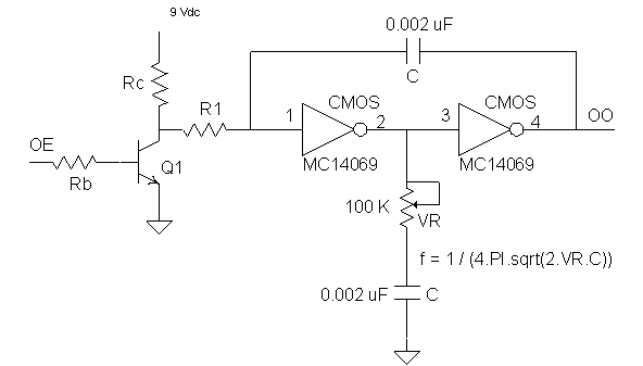
The circuit above is basically an oscillator circuit based on the CMOS part MC14069 HEX inverter. Variable pot VR will vary the operating frequency as per the values of C and VR. You may place a series resistor of you own (may be start with 100 ohms or a bit higher) with VR to prevent VR from going to 0 ohms position at the extreme. It really won't hurt if VR goes to 0 but it doesn't look nice on the scope. I personally didn't like it. Increasing C value will decrease the frequency and vice versa. You may replace Q1 with low power MOSFET but I chosen to place NPN in this circuit. Be careful not to introduce large capacitor due to gating the Collector-Emitter of Q1 with the CMOS inverter as this may alter the operating frequency. Q1 basically will shutdown or enable the oscillator circuit via Oscillator Enable OE pin which is the side of Rb opposite to the base of Q1. If OE goes HIGH the oscillator will shut down. If it is LOW the oscillator is enabled. You may need to use a voltage divider at Rb. For 5 volts operation use Rb of 1 to 5 Kohms. Select a value for Rc of about 800 Ohms to 1 Kohms. R1 should be high enough to present isolation so frequency is not affected. You may also use a 100 Kohms variable resistor in place of R1 depending on selection of Q1. Start with about 5 Kohms for R1. If more isolation is needed then increase the value of R1 depending on Q1 selection. Q1 could be any low power NPN BJT transistor with minimum collector to emitter capacitance. Start wit 2N2222 for Q1. Start with Fine tuning the operating frequency from VR as the final HIGH VOLTAGE is dependent on the value of VR. Lower frequencies may not be at your side to generate higher voltages but is useful for low voltage applications or for repelling the loose dogs and animals by your backyard. Of course we don't want to hurt them but only to gently deter them, insure to lower the voltage from VR for such application and then test it on those he who gave you hard time ... just kidding.
If you connect the Oscillator Output OO above to your oscilloscope you should see a square wave. Now vary VR and see the effect. The nice thing about the CMOS part I used above is that it can operate from 5 volts up to 18 volts DC. The higher the voltage feeding your MOSFET drivers the higher the transformer output voltage and thus the build up on the STORAGE capacitor Ch.
Ok, so now you have the oscillator circuit working. By the way try doing that. I always do that when I build such circuits. Turn ON your circuit above and bring your AM radio close to it... Tune your AM radio to blank station so you can hear that, now vary VR and observe the funny sounds coming from you radio... huh...
Take 5 min break and come back again.
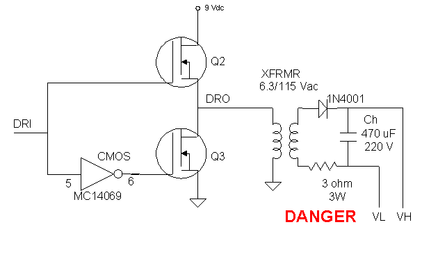
So you are back... Now build the following Driver/Storage Circuit (DSC) below:

The capacitor Ch above can have other values than 470 uF but voltage rating should be compatible with your application, failure to do that may cause the capacitor to explode. Try to use for example 22000 uF cap at 500 volts or higher for beefy results. You may ask what sources available for the transformer and the MOSFETs Q2 and Q3? Well they are all at Radio Shack store closest to you or can be ordered from Digikey or Mouser. What power rating are these transistors? Well it depends on your application. Do you want to electrify your back yard or do you want to display your Tesla coil, or just to demonstrate on lower voltages such as 50 up to 200 volts. Look at the specs of the transistor and you decide what you want to buy. As a starter you may want to buy IRF511 the N Channel MOSFET commonly used in many applications. Again search google for specs of any transistor you are interested to use depending on your application. The choice is yours. The transformer I included in this circuit is from Radio Shack, when you go there ask for a power transformer 6.3/115 Vac. If you use the fly back transformer or different transformer you will get different output voltages depending on the TURNS RATIO. Each transformer needs to tune for its frequency from VR above.
**************** CAREFULL *****************
Now the HIGH VOLTAGE part.
Turn OFF the oscillator circuit before you do any thing for now. Please keep your fingers away from the secondary wires of the transformer. Points VL and VH at the right side of the Driver circuit can be harmful if you touch while oscillator is ON. I warned you...Well after you build the DSC above connect point DRI (DRiver Input) to point OO of the oscillator circuit.
Remember that the 9 volts shown on the Drain of Q2 MOSFET can be from 5 up to 50 or even higher. Make sure you connect grounds of all circuits together. Note that the TRANSFORMER SECONDARY is completely isolated from the primary circuit. At this point make sure your power supply is OFF. Make sure all wiring is correct. Now apply power to the oscillator and Q2 Drain. Use the oscilloscope to measure the voltage between points
VH and VL. Do not touch these two points as they may cause harm. Now vary VR above and observe how the voltage on the oscilloscope varies with the setting of VR. At certain setting you will hear the transformer hissing at higher frequencies as ssssssss. This hissing is similar to the hissing of your old camera flash light.Now disconnect all power from the circuit and use the insulated screwdriver (plastic or wood handle) to short circuit point VH and VL. Failure to short these two points may cause you an accidental electrical shock. Insulation of the screwdriver with a plastic handle or similar will protect you from getting the electrical shock.
NOTE: *** Do not discharge the storage cap of other high voltage circuits with this method as this may cause damage to your equipment. The safest way of discharging, if you don't know the proper discharge point, is to wait for an hour or so after you disconnect power ***.
Now build the following LOAD circuit:

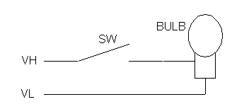
This is basically a bulb (say 12, 20, 50 or more volts depending on your VR setting) mounted on a socket and a switch to turn on the bulb. The last LOAD circuit is pretty simple. The bulb power rating should match the power ratings of your selection. Assuming using above circuit start by using 12 volts bulb with VR set at low frequency. Use your voltmeter or oscilloscope to measure the voltage buildup on Ch capacitor. Please give it some time to store energy (electrons) to its full capacity. You may also try to use the Holiday Decoration bulbs. I bought 20 bulbs from Wal-Mart for less than a dollar during the holiday season and had them with me since then. When I tried them in my circuit their intensity was almost 20 times stronger than when used with the intended operating voltage. They are rated at 12 volts continuous but in this application the voltage is in a form of a pulse and power is de-rated accordingly. My eyes were intimidated because of the intense brightness they produced. I blow up couple of them initially until I adjusted VR to a level where my bulbs are not blowing up any more. The VH and VL in the LOAD circuit should connect to the VH and VL of the DSC Driver circuit above. Insure that VH of LOAD goes to VH of DSC Driver circuit and VL of LOAD goes to VL of DSC Driver circuit. The LOAD circuit above uses a momentary push button switch that will causes the capacitor Ch to discharge.
CAUTION: Insure that the SWITCH SW is insolated so you don't get shocked when you press it.Now adjust your oscilloscope (if you have one) to measure 50 volts per division, connect your oscilloscope probe to the pins of Ch capacitor, turn POWER ON, count to ten while looking at the oscilloscope. You should see the build up of DC voltage on the capacitor Ch. Wait untill it stabilizes. Now adjust your VR until you hear the hissing sound from the transformer or until you read the maximum voltage from Ch. Use voltmeter or oscilloscope to measure the voltage at points VH and VL. Adjust VR to get maximum voltage reading while you should still hear the hissing sound. Counting to ten or 5 will give the capacitor Ch enough time to charge to its full capacity and this also depends on the operating frequency selected by adjusting VR. Different frequencies will produce different voltage levels at VL and VH points. If you wish you may experiment with higher capacitor values but insure that their voltage rating is at least two times the highest generated voltage. I would keep a large capacitor with me all times with voltage rating of at least 500 or more. Be ware if you use very low voltage rating capacitor you may then explode it.
How to operate this circuit: Power up your circuit, count to five or ten, then press the switch button SW. The bulb should flash with very high and intense brightness. The longer you count (or wait) the more intense the light will be. You can still use bulbs rated at much lower voltages than the output at VH and VL if you carefully set VR and also because bulbs can be de-rated since the discharge time is very short. Any way, be prepared to burn couple of bulbs until you come up with the proper VR setting. It took me 3 small 12 V bulbs and 2 holiday bulbs until I found the correct setting of VR. This is experimental and is left for you to try...
Let's take a quiz for now: How do you know when is the right time to press the SW switch and lit the bulb? The answer is by adding a 1. voltage trigger circuit or 2. Timer circuit. By using the voltage trigger circuit the switch will be closed electronically when the voltage at the Ch capacitor reaches to certain predetermined level. This uses a voltage divider resistor network with Zener diod for reference voltage, comparator Op Amp, and power MOSFET transistor as a switch in place of SW. The timer is not very accurate but if you know how long it takes for your circuit to charge the cap Ch to a desired level then you can set the timer to cause a delay for that much of time and then trigger your switch SW electronically via power MOSFET. This is the principle of your old camera flash light. The ready LED lits ON when the voltage on the cap reaches certain level awaiting for you to press the flash push button.
Browse my other pages to find out how to design and build a timer circuit that could be used with this circuit.
Having fun yet...
![]()
By Engineer: Firas Faham
Damascus Syria