1. ROBOT LOCATION AND DETECTION
3. BEACON TECHNICAL SPECIFICATIONS
3.2 Instructions for mounting the beacon
3.4 Electro Optical Specifications
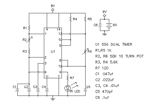
Each beacon emits a 40 KHz IR signal, similar to that emitted from a television remote control. (Television remote controls can have an IR carrier anywhere between 25 KHz and 100 KHz, though.) The suggested receiver is of the exact type used in a television set. This allows the robot builder to buy a ready made receiver that has decent range capability and costs less than five dollars.
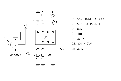
When the remote control receiver receives the beacon, it responds by putting out a wave form of the frequency sent out by the beacon. The frequencies are 550 Hz, 700 Hz, 850 Hz and 1000 Hz.
The high power IR beacons and good receiver sensitivity cause the range to be quite long. The calculated range for the system is greater than 30 feet. (The measured range in a fully lit arena (1996) was the full arena length. No one can guarantee this range for your IR modules, although thirty feet or greater should be easily attained.)
If one chooses not to distinguish the beacon frequencies, this high power, long range system has a possible problem. If the robot looks for just any signal, then the robot could see its own beacon's reflection on a nearby object. It could then attack the wall or nearby object. It could remain on the wall for the duration of the match. The calculated beacon/receiver reflection range is about five feet but could be much more (two to three times, or even more) in some circumstances.
There will be some jitter in the received pulse train, especially at the longest ranges. This jitter may change the pulse width of the received wave form. The frequencies are purposely placed 150 Hz apart to allow one to deal with pulse jitter either in software or hardware.
One recommended receiver module is manufactured by LITEON. It is called an "Infrared Remote Control Receiver Module" and is available from Digi-key. This part is active low (i.e. when it sees 40 KHz the output is low). Digi-key's part number is LT1060-ND. Be sure to get the 40 KHz module. The cost for the module in early 1997 is $2.88. (If your total order from them is less than $25.00 they will add a $5.00 cost for "handling".) Digi-key's phone number is 1-800-344-4539. They are hobbyist friendly and will send a catalog if requested. Parts for the tone decoder circuit shown below are also available from them.
The Infrared Remote Control Receiver Module is also available from Radio Shack (Cat. No. 276-137). Follow these links to the data sheet and sample applications. If buying from Radio Shack be sure to get a 40 KHz module as some of the modules they sell are the 38 KHz module. Although a 38 KHz module will receive the beacon's pulse, it will have limited range, and much more jitter than desired.
The reception, demodulation and tracking of the beacon information shall be to the discretion of the individual warbot builder.
(The technical information presented here is only to spark the creativity and possibly assist the warbot builder. It is provided only to give the builder some suggestions. There are many more methods that would work well. Some methods may work better than others. There are many more software and hardware methods, but would take too long to describe here.)
For example, when looking for 700 Hz the algorithm might be;
IF
[ (the positive pulse width is greater than 645 uS)
AND
(the positive pulse width is less than 800 uS) ]
THEN
beacon frequency is 700 Hz
One could also look at the negative pulse width, or both, or even do an FFT and look for the frequency that way. Using software to sort things out has the advantage of having less hardware (i.e. less things to break). There are many more ways to do this in software. Here are code examples for a PIC and a Basic Stamp I.
The signal is ready to be used whenever one checks for it. This can free up processor time if needed. Also, if desired, a processor is not required to make a robot attack the other, as relay logic could be used to drive one robot into the other. There are other hardware methods such as peak detection, pulse gating, etc.
*If bolting, slightly (1/16") oversized is wise, to allow easy mounting.
The beacons used for the autonomous competition emit an infrared (IR) signal. The beacons transmit IR (880 nM) in a 360 degree ring in the horizontal plane and 18 degrees (-3db) in the vertical plane. This ring power currently is 500 mW IR into a 360 degree by 18 degree angle.
Emitted power remains constant thorough the battery life. Each beacon has a low battery indicator that indicates a low battery about 15 minutes before the output IR power is reduced.
The IR signal carrier is modulated at 40 kilo hertz (on 12.5 uS, off 12.5 uS) 100% modulation. This carrier signal is then modulated at 550 Hz (on 909 uS, off 909 uS), 700 Hz (on 714 uS, off 714 uS), 850 Hz (on 588 uS, off 588 uS), or 1000 Hz (on 500 uS, off 500 uS).

