Latest revision Jan 5
Light is a form of electromagnetic energy that can be detected by the human eye, that's the key part of the definition.
Light travels in the form of a travsverse wave and as such may be defined in terms of a wave function; the simplest being f( ) = A sin. Phase sifts will be ignored.
Rectilinear propagation of light describes the fact that light travels in straight lines and you should remember this fact from studying the pin-hole camera.
What's the electromagnetic spectrum? Well here's a diagram to show you
But this still doesn't tell you how a ray or beam of light is produced. Light beams come in bundles of energy called photons and how are these produced?
Objects that produce light are called luminous objects and those that don't are non-luminous. Non-lumonous objects reflect light, that is why they are visible. Since visible light comes in many different frequencies or colours, and non-lumonous objects absorb some of these frequencies, most objects are seen in thir reflective colour. A green leaf will absorb all the colours except green. This frequency is reflected and detected by your eye and your brain says "green".
Transparent objects allow light to pass directly through the material and as such are studied.
Translucent materials scramble the light beams as they pass through and essentailly are not studied.
Opaque objects do not allow light beams to pass through instead reflecting lightwaves per colour of the object.
The quantum model of light is somewhat of a combination of the particle model and the wave model of light, since these two explinations or models cannot explain all of the phenomenae of light.
Characteristics of Light
Rectilinear propagation describes the fact that light travels in straight lines through a uniform medium. If the medium is not uniform, then the light rays may not travel in straight lines but may be bent. An example of such an effect is a mirage.
When light rays reflect or bounce off a object or surface the angles between the incoming ray and the reflected ray must be equal. Note: both angles are mesured to the normal.
| Reflected Ray |
 |
Incident Ray |
The incident angle i always equals the reflected angle r
Both i and r are measure from the normal
The normal is drawn as a dotted line to the reflecting surface at the exact point where the incident ray strikes the surface. This point is called the point of incidence.
REMEMBER all angles are measured to the normal, in all optical measurements.
Key words and terms that you must be familiar with:
ray ��� ���beam ��� ���parallel beam��� ���converging beam ��� ���diverging beam ��� ���transparent ��� ���translucent��� ���opaque

Have you ever noticed that when you put a spoon or straw in water that it seems split into two sections at the surface of the water? This phenomena is called refraction.
Activity done: Penny in crucible with water added.
The speed of light is a function of the medium through which it travels. It has its greatest velocity in vaccuum 2.9979 x 10⁸ m/s or 3.00 x 10⁸ m/s (three digit accuracy). As the medium becomes more dense the speed of light decreases. See table 10.1 in your text book for exact values. The actual velocities are not gnerally used, however the ratio of speed of light in vacuum to speed of light in a particular medium is much more useful. Because the speed of light in a vacuum and air are almost the same, the term index of refraction will be defined as the ratio of the speed on light in air to the speed of light in the medium under study.
Because it is a ratio the index of refraction has no units. Usually a table of values is provided in your text book for index of refraction values.
Experiment #1: Determining the Index of Refraction for either lucite (methyl methacrylate) or water.
Experiment #2: Determining the critical angle for each of these substances
As you should know light is made up of different colours, which all travel at more or less the same speed in vacuum and air. The important thing to note is that different colurs travel at different speeds in a material medium. The index of refraction for a specific colour is a constant for a specific medium but changes from colour to colour. This is why this happens.

and each colour bends at a different angle.
Activity done: viewing the spectrum of a white mercury vapour lamp with a diffraction grating.
To explore different colour rays bending through a prism with an ability to measure angles Click Here
Snell's Law
A ray of light passing from one medium to another will be bent on passing into the second medium.
| Incident Ray travelling in a less dense medium |
 |
Refracted Ray, bent towards the normal,
passing into a more dense medium
|
By density I mean optical density. The more dense the medium the great its index or refraction.
For an explination as to why a light beam bends and on the second page accurate, analytic representation of incident and refracted ray angles for different materials just
Click Here
and another site in which you can change n1, n2 and the angle of incidence 1. You can also switch between a ray and a beam and view reflected rays also.
Click Here
The relationship between the angle of incidence and the angle of refraction is called Snell's Law. The equations may be stated as follows:
The second equation is valid when you are passing from air to another medium because n1 is approximately equal to 1.00 and the n value quoted will be the index of refraction of the medium being studied. This concept is used in the lab exercise.
Everything remain the same when passing from a more dense material to a less dense one. As you can see in the diagram n1 is > than n2.
Experiment #3: An activity that will be done to emphasize light passing through both situations will be the Lateral Dispersion Lab

Total Internal Reflection

This situation will occur only when a beam or ray of light is trying to pass from a more dense medium into a less dense medium. Because the angle of refraction is bending away from the normal and as the angle of incidence increases, eventual the angle of refraction will become 90o. This incident angle is called the critical angle and the refracted beam travels parallel to the surface of the two mediums. As the incident angle is increased more the beam or ray becomes reflected inside the medium. This is called total internal reflection
To view this phenomena & see two uses just Click Here
Uses of total internal reflection are binoculars, periscopes fiber optic cable. Your text book has pictures of each.
For a more complete note of Fiber Optics
Click Here
Apparent depth is a phenomena based on light rays travelling from an object in one medium being refracted on passing into the second medium , causing what appears to be a bending of the object. See the above diagram of the straw in water. This causes the actual depth (d) to be viewed at a different position than where it actually is. The position of this image or apparent depth (d') is in the ratio of the two refractive indices of the two mediums. Because of the complexity of the math, only those situations where the observer and object are on the normal, will be computed.
The formula is d' = d (n2/n1) where n2 is the refracrtive index of the medium in which the observer is located and n1 is the refractive index of the medium in which the object is located.
More often than not this is a air to water situation.
Curved lenses are used to control and focus the bending of a beam of light.
There are two main classification of lenses: convex & concave.
Lens terminology that must be known: � � � � � angle of deviation � � � � � converging lens � � � � � diverging lens � � � � � principle axis � � � � � axis of symetry � � � � � focal length � � � � � radius of curvature � � � � � focal plane � � � � � virtual image � � � � � real image
It will be expected that you familiarize yourself with terms.
Converging Lens
Without further adieu check these two out
Diverging Lens
Another applet Diverging Lens with Sliding Object
Lens Summary
The following table gives summary of object - image characteristics for converging lenses
| object position |
image position |
| at infinity |
a single point at F |
| beyond 2F |
real, inverted, smaller, between F and 2F |
| at 2F |
real, inverted, same size, at 2F |
| between 2F and F |
real, inverted, larger, beyond 2F |
| at F |
no image; parallel rays |
| close than F |
virtual, erect, larger, on same side of lens |
 In this diagram parallel rays from infinity pass through a convex lens and are focused to a point. This point is the focal point. This technique can be used to experimentally determine the focal point of a convex lens.
�
�
�
The following table summarizes diverging lenses.
| object position |
image position |
| at infinity |
a single point at F on same side of lens |
| closer than infinity |
virtual, erect, smaller, on same side of lens |
 In this diagram parallel rays from infinity diverge and if traced backwards, thsy will meat at the focal point of this lens.
�
�
�
Ray Tracing
You must be able to draw ray diagrams given various sets of information and be able to deduce the unknown quanties. Taught item in class so follow closely and for review just go to 
On viewing you will see that this site shows you step by step how to draw a ray diagram for both a convex and a concave lens. Where the three rays intersect is where the image is formed. (Ignore the mirror drawings)
Thin Lens Equations
Thin lens equations are based on the following diagram
 The one equation relates distances to focal length and the other is a magnification formula which is a ratio of object/image height to the object/image distance.
Working with and using these equation will be a taught item.
You must be aware of the sign convention used in lenses;
- the height and object distance is always positive
- the height of the image is positive if the image is upright and negative if the image is inverted
- the distance of the image is positive if the image is on the opposite side of the lens from the object and
negative if the image is on the same side of the lens as the object
Optical Instruments
Instruments, devices that will be looked at are as follows:
A diagram of these devises may be found by Clicking Here
- Hand Lens or Magnifying Glass
- Compound microscope
- Overhead or slide projector
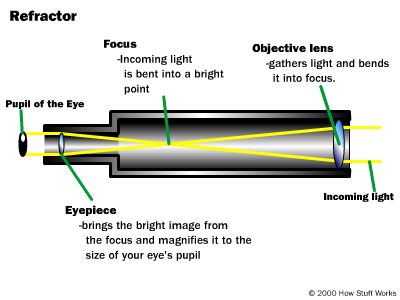
- Telescopes; astronomical, Galilean, and terrestrial, make sure you know the differences in construction
This is not a proper ray diagram.
For a proper ray diagram see your text book!
Assignment: to investigate the construction and operation (the lens diagram) of the telescope and microscope. Must compare and contrast the two optical devises.
Each report must include:
- type of lenses used and their nomenclature
- optimal focal lengths for each lens and why that particular focal length is used
- focusing your devise
- object's position relative to the focal length
- proper lens, ray diagram showing how the veiwed object is magnified
- for the telescope only: the difference between the astronomical and terrestrial telescope in construction and viewing differences
Half the group does the microcsope the other half does the telescope. Each group will make a small presentation to the other group.
A group activity with a written report required. A culminating project. Due Friday Feb 22. A presentation format will be expected.
- Camera
- Human eye
Vision correction for myopia, hyperopia and astigmatism
For a look at the eye visit Vision and Eyesight
Short assignment may be given on this topic. This assgnment is a series of questions that can be answered either from your text book or the listed Internet site Just Click Here for this worksheet.
- Addition terms to know: farpont, nearpoint & optical power. Optical power is the inverse of focal point which is measured in meters.
A positive optical power indicates a converging lens and a negative sign indicates a diverging lens.
- To determine the focal length of corrective lenses, employ the thin lens formula in order to position an image of the object at either the nearpoint or farpoint of the eye. Since the image is virtual its sign will be negative. It is the cornea and lens of the eye that produces a virtual image on the retina.
The Microscope
The microscope uses two lenses separated by a hollow tube. The eye which one looks through is called the eyepiece. The lens closest to the object is called the objective lens. The objective lens produces a real image somewhere in between the focal length (fe) of the eyepiece and the eyepiece lens itself. This real image can then be magnified by the eyepiece lens and a final virtual image is then produced.
Sign Convention for Thin Lenses
- The focal length f is positive for converging lenses and negative for diverging lenses.
- The object distance do is always positive for either lens type.
- Real images have a positive distance do is +
- Virtual images have a negative distance di is -
- A virtual image is formed with a convex lens when the position of the object is between the focal length and lens itself. The close the object is to the lens the smaller the image.
- Images in a concave lens are always smaller than the object.
- Inverted heights are negative and are measured downward from the focal plane.
- The magnification m is positive when the image is erect and negative when the image is inverted.